 |
Electricity 101 Tutorial
If your interested to understand the behavior of photovoltaic systems at a deeper level, it makes sense to become familiar with the fundamental principles of electricity that are at play.
What is Voltage?
Voltage (V), measured in Volts (V) is the electric potential difference between two points. The voltage between these two points can be defined as the amount of energy required to move a unit of charge from the first point to the second. Say what!? Ok, that was the technical definition, so now for the layman's explanation.
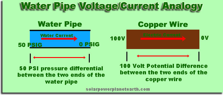
Voltage can be thought of as "electric pressure." The way water pressure and water current are related in a pipe can be used as an analogy to how voltage and current are related in an electrical conductor. In this case, voltage would be the equivalent to the pressure differential between the two ends of the water pipe. In the pipe, the pressure differential between the two ends, pulls (or pushes) the water from the high pressure end to the low pressure end. Voltage, has the same effect across an electrical inductor by moving the charge from the higher potential to the lower potential. The more water pressure, the more water current, and therefore more voltage, more electrical current.
What is Electrical Current?
Current (I), as measured in Amperes, or Amps (A), is the flow of electric charge through a point per unit time. In a conductor such as a metal, there are "free" electrons, which roam freely between different atoms within the material. When a voltage is applied across different ends of the conductor, the electric field created causes the free electrons to immediately flow through the conductor from one end to the other, creating an electric current.
Ok, back to our water pipe analogy. In the description of voltage, we said the pressure differential in a water pipe moves water through the pipe from the high end to the low end, creating a water current. The water current in a pipe is analogous to the electric current, or flow of electric charge in a conductor. A water pipe analogy is shown in the graphic below for clarification.
How Much Current will Flow Through A Conductor When A Certain Voltage is Applied?
This question is best explained by defining Ohm's law, which relates voltage, current, and resistance. Ohm's law states that when a voltage (V) is applied across a resistance (R), a current (I) shall flow across that resistance. This relationship is shown in equation (1) below.
![]() OR
OR  (1)
(1)
So as an example, if we had a wire, that had 10 Ohms of resistance from one end to the other, and applied a voltage of 100V across that resistance, according to Ohm's law, we would get 10 Amps of current flowing through that wire, as is shown in equation (2) below.
 (2)
(2)
Power (Watts)
Power is energy per unit time. In the world of electricity, power is defined as the voltage times the current, at a given point in time, and is shown in equation (3).
![]() (3)
(3)
where P is power in watts, V is voltage in volts, and I is current in Amps.
Alternating Current (AC)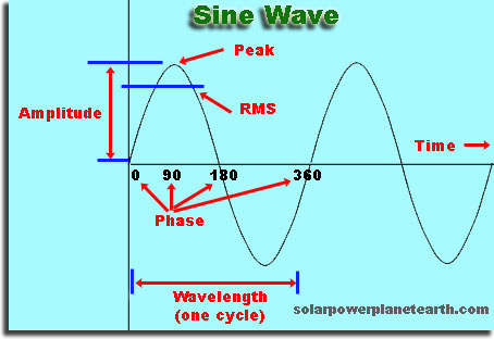
Alternating current is one that changes directions X number of times a second. This rate of change is known as the "frequency" and is measured in Hertz (Hz), which is defined as "cycles per second." The voltage and current waveforms for alternating current follow that of a standard sine wave and is shown in the graphic to the right.
Amplitude - This is the absolute height of the sine wave from it's zero point to the peak.
Peak - This is the highest point on the sine wave. Keep in mind that there is also a negative peak on the opposite end, which has the same magnitude as the positive peak.
Wavelength - A wavelength constitutes one cycle of the sine wave. A cycle can be defined as having gone through a positive and negative peak and returned to the zero point. From the wavelength, we can determine the frequency through the relationship shown in equation (4).
 where
where ![]() wavelength, (4)
wavelength, (4)
and v = velocity. Since we are dealing with electromagnetic waves, the velocity in our case will be equal to the speed of light, c, which equals 299,792,458 meters per second (or roughly 186,000 miles per second) in a vacuum. The power that is used in your home (in America) uses a frequency of 60Hz, or 60 cycles per second.
Phase - The phase of a sine wave is the starting point or initial zero crossing for a given period, and is measured in degrees (0 to 360 degrees) or radians (0 to 2π). Considering the figure above again, if we had a sine wave that started at the 90 degree phase point, we could say that particular sine wave had a phase of 90 degrees relative to our reference point of 0 degrees. The generalized form of the sine wave equation in degrees is shown in equation (5).
![]() where
where ![]() = phase, (5)
= phase, (5)
A = amplitude, f = frequency, and t = time. This equation can be used to calculate any point on the sine wave as a function of time.
RMS = RMS stands for Root Mean Square. This is the common value used when describing AC signals since the AC signal is constantly changing. It is defined as a statistical measure of the magnitude of a varying quantity. It can be seen as an average.
 OR
OR ![]() (6)
(6)
An example of how RMS is used would be your household AC, which you know as 115VAC. This in fact refers to the RMS value, and not the amplitude. Using equation (6), you will see that the amplitude of the 115VAC signal in your home is around 162VAC.
Direct Current (DC)
Direct current is really just a special case of Alternating Current. Direct current is alternating current with a frequency and phase of zero. If you insert zero into equation (5) for frequency and phase, you will see that you will be left with y(t) = A, which means it is always one amplitude in one direction.
The "Kilo-Watt-Hour" (kWh) Unit of Energy
As you have probably noticed, your utility company charges you based on the number of kWhs you use each month. So how do you relate this measure of energy with how much power each appliance you use in your home consumes? Recall that we defined power as energy per unit time. Knowing that definition, we can simply multiply the power consumed by the amount of time it was consumed to get the amount of energy used. The relationship between power (watts), and energy (watt-hours) is shown in equation (7).
![]() (7)
(7)
In order to get kilo-watt-hours from watt-hours you simply divide the number by 1000, as shown in equation (8).
 (8)
(8)
Using the equations above, we can calculate the amount of energy that a given appliance will use per month. As an example, we shall calculate the amount of energy a television will consume for one month. Lets assume the television uses 100W of power when it is on, and is typically used for 4 hours a day. Assuming 30 days in a given month, we first multiply 4 hours by 30 days to get total of 120 hours the TV is used each month. Now using equation (7), we multiply 100W by 120 Hours to get 12,000 watt-hours (Wh) of energy. We then divide that number by 1000 as shown in equation (8) to get 12 kilo-watt-hours (kWh) of energy. To conclude, your television will use approximately 12kWh of energy per month. If your charged 14 cents per kWh of energy you consume by the utility company, it will cost you $0.14/kWh x 12kWh = $1.68 per month to run your television for 4 hours a day.
How Much Electricity (Power/Voltage/Current) Does it Take to Shock You?
We first start by saying, it is the amount of current which passes through your body which determines the lethality and shock effects, not the voltage or power. Voltage and power are indirectly related to shock.
This is a fairly complicated question, so it shall be broken down into two simple cases, namely, how much current does it take before you feel a shock, and how much current does it take to kill you. Really, it depends on if it is AC or DC, the path of the current through your body, the frequency, the resistance of your skin, etc; however, to keep things simple, it takes about 1mA of current before you feel it, and 60mA through the chest to cause ventricular fibrillation of the heart muscle, which usually leads to death. AC is generally considered more dangerous than DC since it can cause your heart to loose coordination at a lower current (the 60mA mentioned above).
Recalling how Ohm's law relates voltage and current in equation (1), and knowing how much resistance the human body has, we can determine how high a voltage is needed to deliver a lethal current. The resistance of human skin varies greatly depending on if it is dry, wet, or broken (a wound). It can vary between 1000Ω and 100,000Ω depending on the previously mentioned conditions. If you assume worst case scenario, having wet skin or an open wound, how much current would be pushed through your body if you came in contact with the 115VAC used in a typical home? Using the same method shown in equation (2), we get:
 OR
OR ![]() (9)
(9)
As you can see, 115mA is well above the 60mA needed to stop your heart, so being exposed only a fraction of a second to 115VAC in a worst case scenario is enough to be lethal.
How Does A Transformer Work?
A transformer uses an oscillating magnetic field to transfer power between two physically independent coils of wire. This means power going into one coil is transferred to coil two without actually being physically connected. Neglecting losses in the transformer, the power going into coil one must equal the power being delivered out of coil two. Coil one is referred to as the "primary" coil, and coil two is referred to as the "secondary" coil, which essentially create an input and an output for the transformer. The ideal transformer will display the characteristics shown in equation (10).
 (10)
(10)
where where V is the voltage, N is the number of windings, I is the current, and the subscripts P and S refer to primary and secondary coils, respectively. Equation (10) tells us that depending on the ratio of the number of windings in each coil, we can step the voltage up and current down, or the voltage down and the current up, all the while maintaining the same level of power.
For example, if we had a transformer with a 10:1 ratio of secondary to primary windings (10 on secondary coil, and 1 on primary coil), the voltage on the secondary side would be 10 times that of the primary side, in addition to the current on the secondary side being one tenth that of the primary side.
"Phase Lock"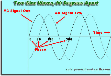
Recall from the description of an AC sine wave above that a sine wave has a phase associated with. There are many instances in communication systems as well as grid-tied photovoltaic systems that locking the phase of two different signals is required for functionality. In the case of photovoltaic systems, you are wanting to back feed power into the utility grid, and therefore need to connect your inverter AC to the grid AC. Since the voltage level is constantly changing in an AC signal, what happens if you connect two AC signals of the same amplitude that are out of phase to each other? You will create a voltage difference between the two signals and create a large current over the small wire resistance connecting your systems. This large current would probably be sufficient to destroy your system. Having said that, the phases must be "locked" so that the two independent AC signals are in step. The figure above shows this graphically.
A good way to think about it is a shift in time. Assume one AC signal was started before the other, both starting at the zero voltage point. This time difference (leading or lagging) will lead to a difference in phase between the two signals.
A solar system inverter needs to phase lock it's output to the grid in order to back feed power in a controlled manner.
"Split-Phase" 240VAC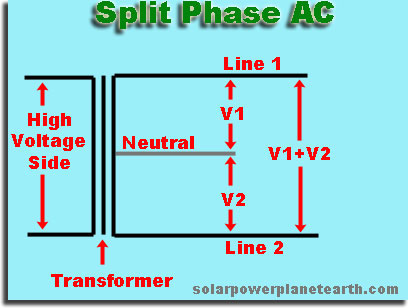
Split Phase 240VAC is a common delivery method for the utility to use in residential applications. On the secondary side of each transformer on a utility pole, there are three wires. Line 1, line 2, and neutral. Split phase refers to a single phase AC signal, that is "tapped" in the middle. From the figure to the right, you can see there are potentially three different voltages created with this method. In the case of the utility, the transformer is tapped in the middle, making V1 equal to V2. Knowing the utility V1+V2 = 240VAC, this allows us to conclude that V1 and V2 are equal to 120VAC, and is where the 120VAC available at each of your outlets comes from.
Why do we use AC instead of DC in our homes?
High voltage is better for long distance transmission (see section below), but we use low voltage in our homes. The high voltage on the transmission lines must be "stepped down" before it can enter your home for practical use. Voltage conversions are done very easily with AC using transformers, as explained above. In order to convert DC to a different DC voltage, you must first convert it to AC, then back to DC. Additional circuitry and power loss would be associated with these unnecessary steps. If an appliance needed DC to operate, it is much easier to "rectify" AC into DC than the other way around as well.
High Voltage Transmission Better for Minimizing Power Loss
If you recall the definition of power from equation (3) and the relationship of voltage, current, and resistance from Ohm's law in equation (1), we can now combine them to determine power loss in a wire for a given resistance and current in that wire. This mathematical relationship is shown below.
We substitute Ohm’s law, ![]() , (1)
, (1)
into the power equation, ![]() (3)
(3)
to get ![]()
which gives us the equation for power loss in a wire, ![]() (11)
(11)
From equation (11), we can see that the power lost in a wire of resistance R is directly related to the square of the current through it. Resistance of a wire can be minimized by using larger gauge wire, however, that comes with a tremendous increase in cost per foot of wire, and when used over long distances becomes unpractical at a certain point.
Since power is voltage times current, could we just increase the voltage and decrease the current to achieve the same power transfer over the transmission line? Yes! This is how power is transmitted long distances. By raising the voltage, we reduce the amount of power loss in the transmission lines since we are reducing the amount of current flowing through those lines. The "magic" of transformers allows us to step voltages up and down with relative ease, allowing for efficient transfer of power over long distances. High voltage transmission lines are typically energized between 140,000 Volts and 750,000 volts.
Electrical Breakers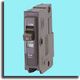
A circuit breaker is essentially a switch designed to open (disconnect) in the event of an overload of current to prevent damage to any circuitry. A breaker has an advantage over using a fuse since it can be reset once it has functioned. Breakers must account for short circuits and electrical arcs. Because of this, they incorporate ways of "extinguishing" electrical arcs internally.
Amp-Hour
Amp-Hour (Ah) is the standard method of rating the capacity of a deep-cycle battery. See our page on deep-cycle solar batteries for detailed examples of how to calculate how many Amp-Hours are needed in a battery array for a given number of loads.
True Sine Wave vs. Modified Sine Wave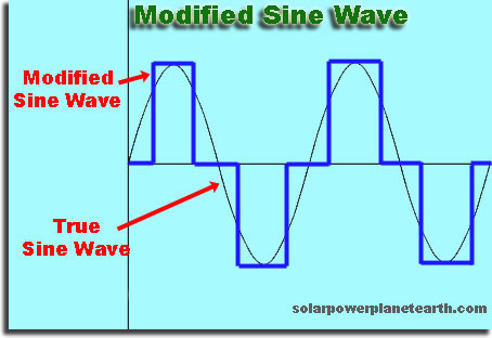
A true sine wave was shown in the above description of Alternating Current. A modified sine wave is used in lower end inverters to save on cost and complete. Certain appliances will not function properly on a modified sine wave inverter.
It is important to note that any grid-tied solar inverter must produce a true sine wave in order to synchronize and back feed clean power into the grid.
A modified sine wave typically uses a square wave to approximate the shape of a sine wave by "stepping" along discrete points. The figure to the right shows a superimposed example of a modified and true sine wave.
A modified sine wave is undesirable since a square wave is the sum of many sine waves at different frequencies. These additional signals at frequencies other than the fundamental (60Hz in our case) are unwanted and end up being wasted power and cause other technical issues with certain electronic devices.
Series vs. Parallel Wiring
When in series, voltages add, currents do not. When in parallel, currents add, and voltages do not.
To best understand this, an example of wiring 10 photovoltaic panels, each with a max power voltage of 50V, and a max power current 5A shall be used. If we were to take all ten panels and wire them in series, their voltages would add giving a string voltage of 50V x 10 panels = 500V. Since currents do not add when in series, the current through the entire string would be 5A. If all ten panels were put in parallel, the currents would add to give 5A x 10 panels = 50A, but since voltages do not add when in parallel, your string would still only have 50V.
Do you see an advantage of wiring the panels one way or the other? There is a significant advantage to wiring solar panels in series. One, you will reduce the amount of wire needed. Two, if you recall from a section higher up on the page, that power loss in a wire is directly related to the amount of current that wire is carrying. By using the series combination, we are only pushing 5A of current through the wire, instead of 50A. For the example we just used, this would translate to a power savings of 100 fold!
If you want to see what these different wiring methods look like, see the bottom of our solar system batteries page.