 |
Solar Power Inverters
Inverters are an essential part of a residential/commercial solar power system. Since the utility grid, your household appliances, and electronics run off of alternating current (AC) and photovoltaic panels produce direct current (DC), solar panel output must be "inverted" from DC to AC to be used. This DC to AC conversion is the job of the inverter, which is typically installed right next to your main service panel by your solar contractor. There are two main types of inverter technologies, central and micro. Microinverters are small inverters that independely invert power from each solar panel. Read more on this state of the art microinverter technology. Below a description of the traditional central inverter technology in provided.
How Does the Inverter Work?
The inverter is essentially an amplified oscillator. An electronic oscillator can be "tuned" to create an AC oscillation at a particular frequency. This AC signal is then amplified using the DC power coming from your panels. In a grid-tied application, this oscillation must be phase locked to the grid AC which allows you to connect your system to your existing electrical panel, and therefore seamlessly go between grid power and solar power when powering your loads. This ability to phase lock to the grid frequency and voltage level is what makes a grid-tie inverter different than simple inverters like those that plug into your cigarette lighter in your car, or a gas generator you take camping with you.
The following diagram shows the generalized layout of a central inverter, inside the purple dashed box:
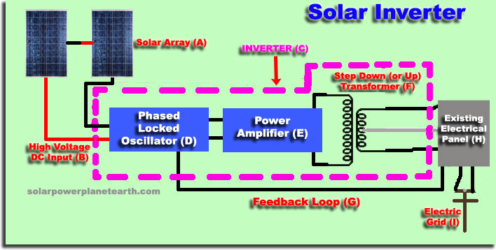
(A) Solar Array
This is your photovoltaic panel array, typically configured in a set of high voltage series strings.
(B) High Voltage DC Input
This is the high voltage DC coming from your photovoltaic panels, and is what is fed into the input of the inverter.
(C) Inverter
The purple dashed box represents what is actually inside a typical inverter. See the descriptions of the individual subsystems below.
(D) Phased Locked Oscillator
The oscillator is the core of the inverter. It creates an "oscillating" electric signal. An oscillator can be tuned to create any number of frequencies, however, in this case, a 60 Hertz (Hz) AC signal is desired, to match the frequency used by the utility grid and all your appliances. It is not good enough to just create a 60Hz sine wave. The sine wave must be phase locked to the utility frequency in order to be connected to it. To better understand phase locking and it's importance, see our electricity 101 tutorial.
(E) Power Amplifier
Once a phase locked 60 Hz AC sine wave is created, it is then amplified through another circuit which uses the full power DC coming from your photovoltaic panels. What you get at the output of the amplifier is 60Hz sine wave with the same power as the DC at the input of the inverter, minus loses from inverter inefficiency.
(F) Step Down (or Up) Transformer
The voltage out of your amplifier is going to be close to the DC voltage at the input to the inverter. This voltage is typically higher than the 120VAC that is needed to power your house, so a transformer is used to "transform" the voltage level by "stepping it down." The power output is kept the same, since the level of current increases as the voltage is decreased in a transformer. This operation can also be in reverse in a "step up" transformer if the voltage from the panels is less than 120V. To better understand how a transformer works, see our electricity 101 tutorial.
(G) Feedback Loop
The feedback loop takes the grid voltage, which is essentially the output of the transformer in your inverter, and compares its phase to the oscillator phase. If they are different, the oscillator circuit makes an appropriate adjustment and eventually "phase locks" the oscillator signal to the grid signal through this method of feedback. Similar circuits are used in electronic communication circuits and are known as "phase lock loops."
(H) Existing Electrical Panel
This is your existing service panel, which contains your utility entrance and all your breakers. This is where the output of the inverter will get connected.
(I) Electrical Grid
The electrical grid feeds into your house through a method known as "split-phase." Most inverters are designed to interface to a split-phase configuration.
WHAT IS ANTI-ISLANDING?
Anti-islanding is used to protect utility company workers in the event of a grid failure. Your inverter is designed to sense both the frequency and voltage of the power coming from the grid, which it then uses to determine if the grid is up or down. If the grid is down, your inverter shuts off, to keep from energizing the lines that are are being worked on by the linemen. This is only required in a grid-tied solar installation.
HOW TO READ AN INVERTER'S DATA SHEET (Inverter Specifications)
As with most electronic devices, inverters come with data sheets which describe the various designed/tested specifications. The following is an example of an inverter data sheet, taken with actual values from a Fronious IG Plus 5.0-1.
| Recommended PV-Power (Wp) | 4250-5750W |
|---|---|
| MPPT-Voltage Range | 230...500V |
| Max. Input Voltage (@ 1000 W/m^2, 14F) | 600V |
| Nominal Input Current | 13.8A |
| Max. Usable Input Current | 23.4A |
| Admissible Conductor Size (DC) | No. 14 - 6AWG |
| Nominal Output Power (Pac nom) | 5000W |
| Max. Continuous Output Power | 5000W |
| Nominal AC Voltage Range | 208V/240V/277V |
| Nominal Output Current | 183-229V (208V) 211-264V (240V) 244-305V (277V) |
| Max. Output Current | 27.3A (@208V) 20.8A (@240V) 18.1A (@277V) |
| Admissible Conductor Size (AC) | No. 14 - 4AWG |
| Nominal Output Frequency | 60Hz |
| Operating Frequency Range | 59.3 - 60.5Hz |
| Total Harmonic Distortion | <3% |
| Power Factor | 1 |
| Max. Efficiency | 96.2% |
| CEC Efficiency | 95.5% (@208V) 95.5% (@240V) 96.0% (@277V) |
| Consumption in Standby (Night) | <1W |
| Consumption During Operation | 15W |
| Cooling | Controlled Forced Ventilation, variable fan speed |
| Enclosure Type | NEMA 3R |
| Unit Dimensions (W x H x D) | 17.1" x 36.4" x 9.6" |
| Inverter Weight | 57lbs. (26kg) |
| Admissible Ambient Operating Temperature | -4 ...122F (-20... +50C) |
Recommended PV-Power (Wp)
This is the maximum recommended input power, in wattage, coming from your photovoltaic array. This number dictates how big of a solar array you can wire into it.
MPPT-Voltage Range
This gives the range at which the Maximum Power Point Tracking (MPPT) will function nominally.
Max. Input Voltage ( @1000W/m^2, 14F)
This is the maximum allowable input voltage, at the solar irradiance 1000W/m^2 and ambient temperature of 14F. This number is specified at a low temperature since the voltage output of a solar panel increases as the temperature decreases. This determines how many panels you can put in a series string, since voltages from each panel add when in series.
Nominal Input Current
This is the nominal current at the input of the inverter, coming from your photovoltaic array.
Max. Usable Input Current
This is the maximum allowable input current, before the inverter will begin to "ignore" further input power, or the point at which damage may occur to the inverter.
Admissible Conductor Size (DC)
This is the allowable wire size that can be used in the DC terminals of the inverter. This is a physical limitation.
Nominal Output Power (Pac nom)
This is the nominal AC power output of the inverter.
Max. Continuous Output Power
This is the amount of output power that can be put out indefinitely with no negative effects.
Nominal AC Voltage Range
This is the nominal range of AC voltages which the inverter can work with. These are broken down into the three standard voltages used in different types of applications.
Nominal Output Current
This is the nominal output current at the nominal voltage your system uses.
Admissible Conductor Size (AC)
This is the allowable wire size that can be used in the AC terminals of the inverter. This is a physical limitation.
Nominal Output Frequency
This is the nominal AC frequency at the output of the inverter in cycles-per-second, also known as Hertz (Hz).
Operating Frequency Range
This is the allowable AC frequency range at the output of the inverter in cycles-per-second, also known as Hertz (Hz). This parameter is typically used in the anti-islanding feature of the inverter.
Total Harmonic Distortion
Total Harmonic Distortion (THD) is defined as the ratio of the sum of the power of all the signal harmonics to that of the power of the fundamental frequency, the fundamental frequency in our case being 60Hz. The lower the THD, the better.
Power Factor
The power factor applies to AC systems, and is defined as a ratio of the true (or real) power to the apparent power. It has to do with the phase angle difference (either leading or lagging) of the voltage and current traveling through your circuit. These phase differences are the result of an unbalance of inductance or capacitance in your circuits. As an example, a purely resistive circuit would have a power factor of one, a purely inductive or capacitive circuit would have a power factor of zero. One is the ideal case. What a power factor less than one tells us is that the circuit must supply more current than it would if the power factor was one, for the same amount of real power delivered to the load.
Maximum Efficiency
This is the manufactures maximum efficiency, usually rated for a specific power level. Efficiency tells us the ratio of the amount of power coming out of the inverter vs. the amount of power coming in. There are losses in every electronic circuit, mainly due to resistive heating.
CEC Efficiency
This is the California Energy Commission's rating of maximum efficiency for the inverter, shown at different voltage inputs. The CEC uses an objective standard with "real world" conditions to rate solar electronics.
Consumption in Standby (Night)
This is the amount of power that the inverter draws to keep itself on when not inverting (standby).
Consumption During Operation
This is the amount of power that the inverter draws while it is inverting.
Cooling
This specification describes the type of cooling used. Different methods of cooling can be more efficient depending on the inverter design. Active cooling can also add to the noise that an inverter makes. The variable fan speed is one of the more efficient designs, since it can throttle down the amount of power that it consumes (and noise it produces) if the heat load is not very significant at the time.
Enclosure Type
This is the type of enclosure the inverter is housed in. The rating is important since it gives the structural integrity and how weather proof it is (i.e. if you can place it in the rain, snow, etc...). For reference, here is a table of the NEMA ratings as they apply to Outdoor Non-hazardous Locations, [from NEMA 250-2003].
NEMA ENCLOSURE TABLE:
| Provides a Degree of Protection Against the Following Conditions: | 3 | 3X | 3R | 3RX | 3S | 3SX | 4 | 4X | 6 | 6P |
|---|---|---|---|---|---|---|---|---|---|---|
| Access to hazardous parts | X | X | X | X | X | X | X | X | X | X |
| Ingress of water (Rain, snow, and sleet) | X | X | X | X | X | X | X | X | X | X |
| Sleet | - | - | - | - | X | X | - | - | - | - |
| Ingress of solid foreign objects (Windblown dust, lint, fibers, and flyings) | X | X | - | - | X | X | X | X | X | X |
| Ingress of water (Hose down) | - | - | - | - | - | - | X | X | X | X |
| Corrosive agents | - | X | - | X | - | X | - | X | - | X |
| Ingress of water (Occasional temporary submersion) | - | - | - | - | - | - | - | - | X | X |
| Ingress of water (Occasional prolonged submersion) | - | - | - | - | - | - | - | - | - | X |
Unit Dimensions
Height, width, and depth of the inverter unit.
Inverter Weight
Weight of the inverter, given in both pounds and kilograms.
Admissible Ambient Operating Temperature
This is the temperature range that the inverter can operate in.
Make sure you check out the new microinverter technology.